
El diseño debe tener en cuenta no solo los procesos de fabricación, sino también la facilidad de ensamblaje para el fabricante de equipos originales (OEM). Durante la fase de producción piloto de un nuevo modelo de automóvil, surgieron frecuentes dificultades de ensamblaje con las tuberías de refrigeración del aire acondicionado, lo que generó costos sustanciales para las modificaciones de diseño posteriores. Al incorporar la ingeniería concurrente en el proceso de ensamblaje final, se aplicaron análisis de ensamblaje virtual y restricciones de diseño durante el desarrollo de las tuberías de refrigeración del aire acondicionado. Esto redujo eficazmente los costos de producción durante el proceso de fabricación y mejoró la eficiencia de la producción. Este documento describe brevemente los problemas de ensamblaje y diseño encontrados en el análisis de ingeniería síncrona de las tuberías de refrigeración del aire acondicionado, junto con sus soluciones, y proporciona una valiosa guía para el desarrollo de tuberías de refrigeración del aire acondicionado en nuevos modelos de vehículos.
I. Introducción a la ingeniería sincronizada para el ensamblaje final
La ingeniería sincronizada (ES) para el ensamblaje final es un proceso que integra los procesos de ensamblaje final en la fase de diseño y desarrollo del vehículo. Consiste principalmente en realizar análisis de procesos de modelos digitales de ensamblaje, líneas de producción, equipos y procesos de ensamblaje, y proporciona modificaciones de diseño de procesos viables para respaldar el diseño. Su objetivo principal es revisar los problemas de diseño del producto durante las etapas de diseño de planos y generación de modelos digitales, tomando medidas efectivas con anticipación para abordar posibles problemas que puedan surgir durante la implementación del proceso, asegurando así que el nuevo modelo de vehículo sea viable para la producción y compatible con los equipos y herramientas.
II. Montaje y diseño de tuberías de aire acondicionado
1. Composición de la tubería de refrigerante del sistema de aire acondicionado del compartimento del motor delantero
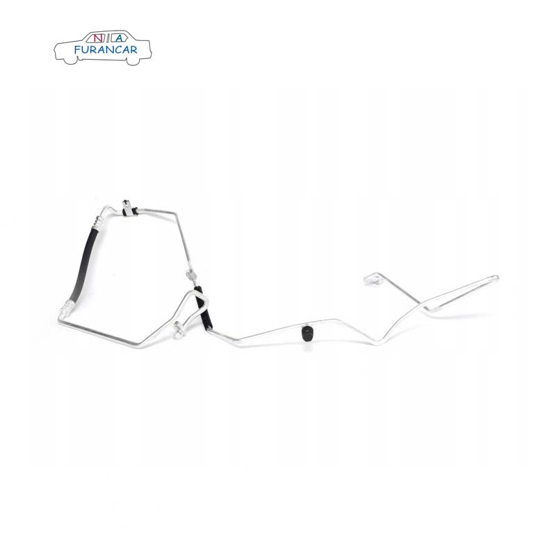
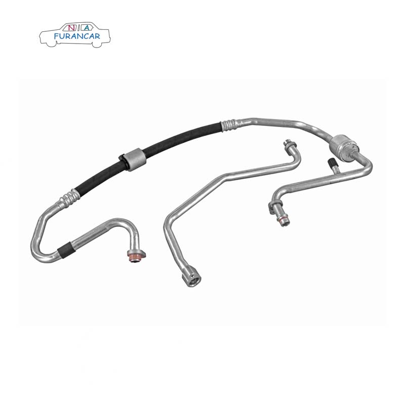
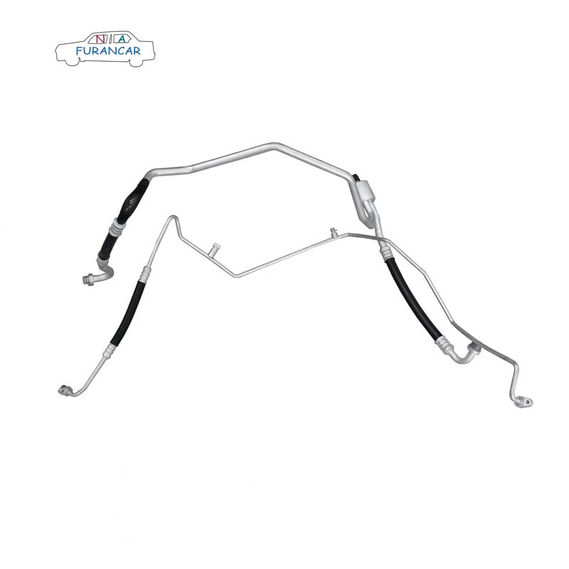
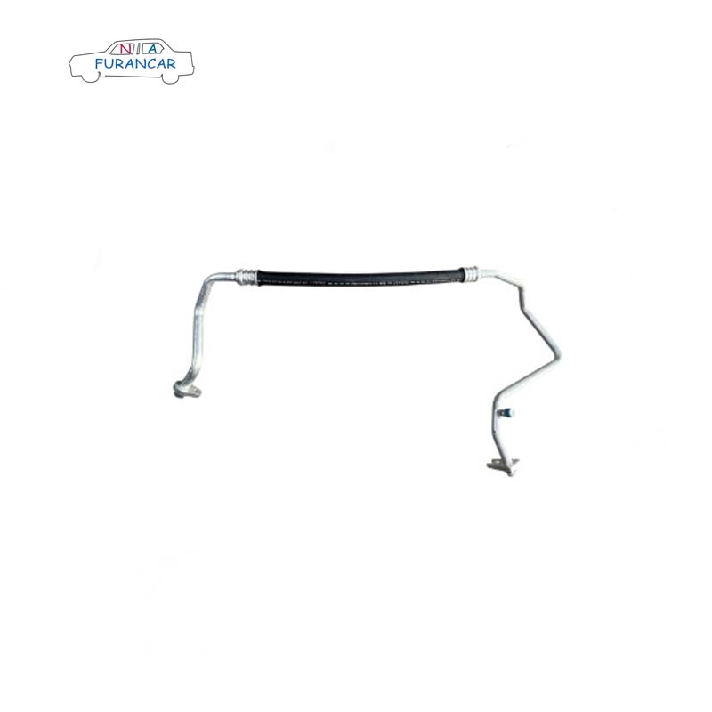
El sistema de tuberías de refrigerante del aire acondicionado comprende principalmente el conjunto de tuberías de alta y baja presión del aire acondicionado, el conjunto de tuberías de escape del aire acondicionado II, el conjunto de tuberías de escape del aire acondicionado I (que puede combinarse con el conjunto de tuberías de escape del aire acondicionado II, según las consideraciones de montaje), el conjunto de tuberías de baja presión del aire acondicionado I y el conjunto de tuberías de alta presión del aire acondicionado I (que puede combinarse con el conjunto de tuberías de alta y baja presión del aire acondicionado, según las consideraciones de montaje).
2. Problemas con el diseño y el montaje de las tuberías de refrigerante del aire acondicionado.
(1) En la conexión entre el conjunto de tuberías de alta y baja presión y la válvula de expansión del sistema HVAC, el acolchado de espuma en las abrazaderas unidas a las tuberías es demasiado grueso y rígido, lo que provoca una interferencia excesiva con el panel frontal y dificulta el ajuste de las tuberías.
(2) El conjunto de tuberías de alta y baja presión del aire acondicionado viene con sus propios soportes de montaje (fijados a los paneles laterales del compartimento del motor y a las vigas longitudinales). Los recortes son circulares, pero el margen de desviación en la dirección X es demasiado pequeño; debido a la combinación de la precisión del ajuste y las tolerancias acumuladas, los orificios de los pernos no se pueden alinear.
(3) Las tuberías de refrigerante del aire acondicionado están conectadas mediante pernos y tuercas; durante la fase de prototipado, el espacio de trabajo es insuficiente para utilizar herramientas de apriete (como una llave de impacto inalámbrica). La interferencia persiste incluso al usar una llave de tubo más corta.
(4) No es posible aplicar aceite refrigerante a las abrazaderas durante el montaje de las juntas de las tuberías, y se producen fugas de refrigerante una vez finalizado el montaje. No existe una sección de manguera flexible que conecte los conjuntos de tuberías de alta y baja presión con el conjunto de tuberías de alta presión; las tuberías rígidas son difíciles de conectar y propensas a deformarse.
(5) El diseño de las tuberías no está suficientemente bien diseñado, lo que genera problemas frecuentes como ruidos anormales y una ergonomía de montaje deficiente; por ejemplo, las tuberías no pasan lo suficientemente cerca del compartimento del motor y el puerto de llenado del aire acondicionado está situado demasiado bajo para permitir el llenado.
3. Restricciones de diseño para las tuberías de refrigerante del aire acondicionado
Las restricciones de diseño son directrices derivadas de una recopilación de problemas comunes que se presentan durante la introducción de nuevos modelos de vehículos y el proceso de creación de prototipos; su objetivo es identificar áreas que requieren mejoras en los diseños de productos posteriores. En respuesta a los problemas de ensamblaje descritos anteriormente, se han establecido las siguientes restricciones de diseño.
(1) La espuma utilizada en la placa de sujeción en la conexión entre el conjunto de tuberías de alta y baja presión del aire acondicionado y la válvula de expansión HVAC debe estar hecha de material PUR, con un espesor preferiblemente inferior a 15 mm.
(2) Con excepción de los orificios de posicionamiento principales, todos los orificios en los soportes de los conjuntos de tuberías de alta y baja presión del aire acondicionado deberán ser elípticos en la dirección X (por ejemplo, 8×10, según la especificación del perno), para acomodar las tolerancias acumulativas. Se deberá proporcionar un mecanismo de restricción de rotación (como un clip de bloqueo) en el punto donde el soporte se conecta a la carrocería del vehículo para evitar que el soporte gire al apretar los pernos, lo que podría causar deformación de la tubería. Los soportes para las tuberías del aire acondicionado deben diseñarse para montarse en las secciones rígidas de la tubería para evitar rayar las mangueras flexibles.
(3) Al diseñar el sistema, se debe tener en cuenta el espacio de trabajo necesario para operar las herramientas de fijación de conexiones de tuberías. Cuando se utilice una pistola acodada, la distancia entre la cabeza del remache y el extremo del perno debe ser mayor de 85 mm; cuando se utilice una pistola recta, la distancia entre la cabeza del remache y el extremo del perno debe ser de 40 mm.
(4) El extremo macho de los racores debe apuntar hacia arriba en la dirección Z (no se requiere la dirección X) para facilitar la aplicación del aceite refrigerante. Las tuberías rígidas no deben conectarse directamente entre sí; debe utilizarse una manguera flexible como conexión intermedia, y la unión debe sellarse correctamente, por ejemplo, mediante la colocación de una junta de estanqueidad.
(5) Por encima de los puertos de llenado de alta y baja presión de los conjuntos de tuberías de alta y baja presión del sistema de aire acondicionado, debe haber un espacio libre con un diámetro de 50 mm y una altura de 250 mm. Además, la separación entre los puertos de llenado de alta y baja presión debe ser razonable (dependiendo del tamaño de la boquilla de llenado).
III. Conclusión
Este documento resume los problemas comunes que se presentan durante el ensamblaje final del sistema de tuberías de refrigeración para una unidad de aire acondicionado automotriz específica. Al incorporar las restricciones de SA en la fase de diseño mediante ingeniería concurrente durante las primeras etapas de la introducción de nuevos modelos, este enfoque ha ayudado a minimizar las deficiencias de diseño, optimizar la capacidad de fabricación del proceso de ensamblaje final y reducir los costos de producción para la empresa. Además, proporciona una valiosa guía para el desarrollo de sistemas de tuberías de refrigeración para nuevos modelos de vehículos.


 Whatsapp :
  Teléfono :
  Correo electrónico :